They are equipped with two single motor bogies, with two gear reduction ratios, making them mixed locomotives (freight or passenger). First to come in 1964, BB 25500 gave way to several other series : |
|---|
Main characteristics of BB 25500 locomotives : Manufacturers : Total length : Mass : 80 metric tons Continuous power (same power under 1500 V DC and 25 KV AC) : 2940 kW / 4000 HP Max. speed in service : 100 km/h /62 MPH (low speed gear ratio) 140 km/h / 87 MPH (high speed gear ratio) Voltage : 1500 V DCand 25 kV 50 Hz AC. |
|---|
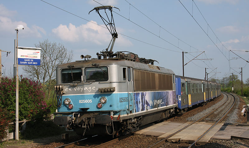 Above : the BB 25605 of Strasburg depot is about to stop in Sanry-sur-Nied station while pulling a train from Rémilly to Metz for the Lorraine TER (Regional Express Trains) activity. It seen here under 25 kV 50, with corresponding pantograph raised.
It bears figure 8, meaning that it was previously used in the Paris suburban services. |
Mechanical part A-Body BB 25600 locomotives as well as BB 25500, BB 8500/8600, BB 17000 and BB 20200 are the direct descendants of the BB 16500. It is therefore logical that their body looks quite similar excepting a few details. The chassis bears two reinforced driving cabs, side panels assembled to it by welding and roof elements bolted. The latter are removable for maintenance purposes like big components replacement : compressor, transformers, etc. The two driving cabs are soundproof and equipped with a functional driver desk similar to the ones of BB 25200 and CC 6500, and an air heater. The BB 25588 to 25694 (as well as BB 8588 to 8646) are equipped with stretched driving cabs (known as « large cabs ») in opposition to BB 25501 to 25587, 8501 to 8587 et 17000 fitted with small cabs. Driving cabs are not equipped with a front chock absorbing system. However, following an accident, the BB 17005 was equipped with special “nose” with such system. This modification was not extended to the other locomotives. The two front glasses are vertical which doesn’t contribute to reduce glare in opposition to CC6500 inclined windshields. The windshield on driver side is equipped with an anti-fog system. |
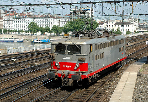
Left : The BB 25585 of Vénissieux depot is seen close to Lyon-Perrache station. It shows the nice "multiservice" livery (but dark grey is a bit faded on this one). On the BB 25588 to 694, body is longer, allowing larger driving cabs. This difference is materialized by the additional window between cab door and front end (see picture below). (Photo APCC 6570) |
|
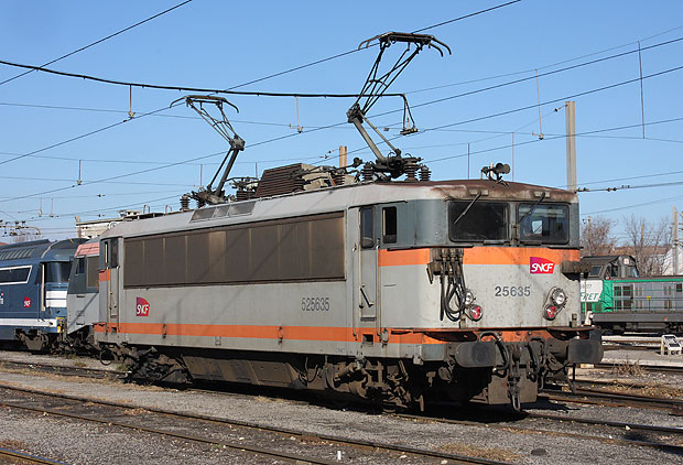 |
Opposite : The BB 25635 "large cab" of Marseille depot, in “concrete” livery, seen in Avignon depot. Notice the two different pantographs which equip the BB 25500 : The 25588 to 25694 have stainless steel vertical louvers on the whole body length. (Photo Pierre Chavernac) |
B-Bogies The very good grip results obtained with the BB 16500 single motor bogies, thanks to their much reduced wheelbase and mechanical coupling of the axles, have encourage designers to carry on with this bogie type on the BB 8500/8600, 17000 and 25500/25600. While grip is excellent due to the reduced when base (which reduces the pitch up effect in traction phase), stability was often criticized by drivers who gave to these locomotives series the nickname of “dancers”. The bogie chassis is made of a welded assembly in which is placed the TAB 660 motor. Each bogie is linked to the body by two drawbars. Braking is done by a brake cylinder (one per bogie) acting on a brake rigging which itself acts on iron shoes applied on wheels (two per wheel). The whole bogie chassis is placed on two beams with helical springs in between, making the primary suspension. The beams are linked to the axles, equipped with conical roller bearings, by an assembly of balls and rods. |
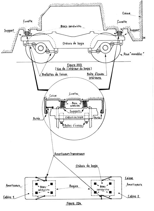 |
The body is placed on bogie chassis with a load-bearing crosspiece equipped with helical springs giving a secondary suspension. This load-bearing crosspiece is placed on the bogie via two conical supports (BB 25501 to 25555). On the BB 25556 to 25694 (sketch opposite), body is directly placed on the bogie through four “sandwich” blocks.
C-Suspension Primary suspension : As mentioned above, primary suspension between axle box and bogie consists in two large helical springs inserted in two beams. Parasite movements are diminished by oil shock absorbers. Secondary suspension : Body is mounted on the bogie chassis with a load-bearing crosspiece (BB 25501 to 25555) or with four “sandwich” blocks on 25556 to 25694. Two anti-yaw dampers (two per bogie) as well as a transversal damper (one per bogie) ensure bogie and body stability. (Opposite : SNCF document)
|
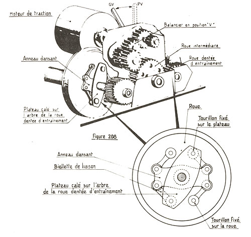
Traction motor is coupled to an external double ration gear reducer with a flexible Citroën coupling. Traction effort is transmitted from reducer to axles by a floating ring drive system. Traction effort transmission to the axles goes through eight gears allowing using the locomotive with two different speed ratios. Lubrication of this system requires a pump driven by one of the gears. This pump takes lubricant in the reducer casing and distributes it by flowing and injection in the bearings. Part of lubrication is made by splashing. |
 |
Reducer Each bogie includes a double ratio gear reducer on top of the bogie. Ratio changing action is manual and can only be done when locomotive is stopped, with main breaker open and brakes on. Ratio changing action is done in the side corridor by opening a door on the floor giving access to motor coupling and reducer ratio switch control. Locking system is actioned by a crank on the corridor wall. An index which first shows V (verrouillé : locked) is brought on D (déverrouillé : unlocked) by rotating the crank. (Opposite: SNCF document)
|
|
During ratio switching, it may happen that gears teeth get face to face and don’t engage.
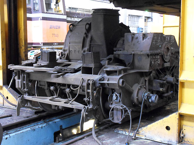
Opposite left : A bogie seen on the reducer side. Suspension “sandwich” blocks are well visible too on the picture. (Photo Victorien Armand)
|
 |
Reducer to axles transmission Reducer is coupled with axles with a floating ring drive, linked, on one side to the reducer and on the other side to the corresponding wheel to drive. This floating ring drive includes silent blocs and tie rods bolted on one of the two wheels of an axle. Bogie can thus moves freely following track imperfection but still transmitting traction effort.
E-Axles BB 25600 have one-piece wheels and axle boxes with conic rollers bearings. Axle boxes are equipped with lubricators to allow regular lubrication as well as temperature sensors to detect an axle box overheat. If this happens, a CB warning for Axle box overheating appears on the dashboard.
Traction circuits The BB 25600 are equipped with two traction motors TAB 660 giving 1470 kW / 2000 BHP. These are classical DC traction motors with a field and an armature with its commutator. They are forced-ventilated. The BB 25600 are equiped with a variator driven by a four cylinder pneumatic actuator. 32 positions can be used. The two direction inverters, the two traction/braking switches and the two AC/DC switches can be actuated manually in the event of a problem on their electro pneumatic drive.
Traction under 1500 V DC : Under DC current, series and parallel connections can be used with 32 variator positions.
1°) Series connection Series connection allows starting a train with a maximum 750 V voltage on the motors. At the end of series connection, variator is on position 20. With main DC breaker closed, when the driver accelerates, variator actuator rotates position by position, eliminating resistances between power supply and the motors. The two motors connected in series are supplied through the rheostat. Progressive elimination of the resistances is made with electro pneumatic switches. At position 20, the rheostat is totally eliminated and voltage at each motor is 750 V. 5 bridging positions are available, allowing increasing or keeping train speed.
2°) Parallel connection Parallel connection is obtained by pushing forward the briding lever. At the end of progression under parallel connection, variator is on position 32. When parallel connection is selected, part of the rheostat is reinserted. Driver then passes variator positions and when reaching position 32, rheostat is totally eliminated. Each motor then gets 1500 V equal to the overhead line voltage. Variator positions were initially shown on the control panel (like on CC 6500). With KVB (speed control by sensors) installation, this was suppressed. Only an “RH” indicating light remain to let driver know that rheostat is not totally eliminated. This light comes off when variator is on position 20 (last series connection position) or position 32 (last parallel connection position). Rheostats are cooled by three fans connected in parallel on a rheostat resistance. They therefore start once current crosses the rheostat and their rotation speed depends on this current. |
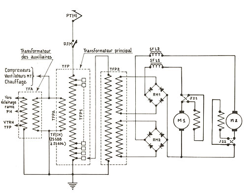 |
Traction under 25 kV 50 Hz AC : Under AC current, on parallel connection is used. 32 positions are used. Current taken from overhead line is supplying the primary winding of an autotransformer through single phased AC breaker. This autotransformer has 32 connections on its windings. Each position change lead to a switch from one connection to the next one. This is done with a oil insulated variator. When on position 32, driver has 5 bridging positions available. |
Autotransformer is equipped with a “heating” output to deliver needed current for passenger trains heating i.e. 1500 V AC 50 Hz. This output also supplies, through a diode bridge rectifier, main air compressor and traction motors fans. Primary winding of auxiliary transformer is also supplied by heating output. Auxiliary transformer supplies at adequate voltage, the main transformer oil pump, rheostat fans and battery charging. The three rheostat fans are on once AC breaker is closed to create an air circulation to cool main transformer cooling fluids. BB 25600 can be coupled in multiple units for heavy trains pulling on difficult profile lines. Anti-skid system : Skid detection is done by comparing intensities absorbed by each motor. Once skid is detected, a light comes on on the control panel, variator actuator stops its progression and goes back of two positions. Sanding is automatically started. A motor armature shunting is done on the motor affected by skidding. High voltage auxiliaries : Battery charging is done under 1500 V using current return from motor fans and compressors. Under 25 kV AC, batteries charging is done with a simple transformer. These systems ensure main battery 72V charging as well as 9V braking battery. Dynamic braking: BB 25600 are equipped with dynamic braking alone or combined with pneumatic braking, as well as emergency dynamic braking. Driver can use 16 levels of dynamic braking. Various equipment: BB 25600 are equipped with following devices : • One AC single phase circuit breaker DBTF ; Text : Victorien Armand |
|---|
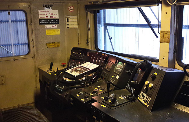 |
BB 25660 control panel. Its structure is quite comparableto the CC 6500 one. (Photo Roland Badosa). |