Main characteristics of CC 6500 electric locomotives |
Symbol of elegance, thanks to talented designer Paul Arzens, speed and power, CC6500 series locomotives have been put in service from the late sixties. They mark the culmination of classic electromechanical technology applied to high speed electric locomotives.
Due to their imposing look (more than 20 m / 66 ft long), their duties on most prestigious French trains (Capitole, Aquitaine, Mistral, ….), their technical characteristics (200 km/h / 125 mph maximum speed, 8000 BHP, 115 to 118 metric tons…), these locomotives have carried French National Railway image before TGV high speed train took over this role.
In 1999, when all locomotives were redistributed by activities, all CC6500 were transferred to freight activity, in which they gave excellent service thanks to their power and their lower gear ratio for lower speeds.
The 74 CC 6500 locomotives were put into service between 1969 and 1975, and are divided in three sub-series.
They were joined in 1995/96 by 4 CC21000 transformed into CC6500, becoming CC6575 to 6578.
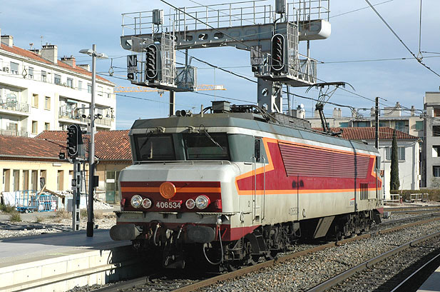
CC 6501 à 6538 Often named as « South-West », they have particularly illustrated themselves on the « Capitole » train from Paris to Toulouse, as well as the « Aquitaine » from Paris to Bordeaux. These locomotives were operated at 200 Km/h / 125 mph. They can be easily recognized to their horizontal ventilation louvers. CC 6534 is seen here at Marseille-Saint Charles station. (Photo Pierre Chavernac) |
 |
|---|
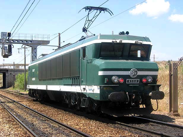 |
CC 6539 à 6559 Known as « Maurienne », they were destined to replace ageing former PLM electric locomotives used in the Maurienne valley of French Alps. Their power as well as their gear box blocked on the 100 km/h ratio made them very performing for such kind of mission. On the first years of their career, they were equipped with shoes to pick-up 1500 V DC current on a third rail. Their austere aspect was made of dark green with white strips. When Maurienne valley line was equipped with overhead wires, their operation was aligned with other CC6500 subseries. (Photo Pierre Chavernac) |
|---|
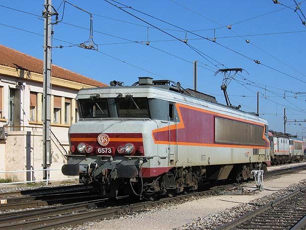
CC 6560 à 6574 Often named as « South-East », these locomotives were mainly used on South-East region and have hauled all express trains of this area and also the « Rhodanien », the « Mistral » or the « Lyonnais » until TGV took over. Also wearing the red and orange livery, they can be recognized to their vertical stainless steel ventilation louvers. Preserved CC 6570 is part of this subseries. (Photo Pierre Chavernac) |
 |
|---|
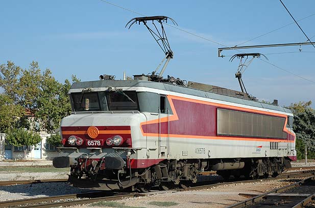
Former CC 21000 In 1995/96, the four CC 21000 able to operate on both 1500V DC and 25000V AC currents, and attributed to Dijon depot have been transformed in CC6500 by Oullins overhaul works to be used only on 1500V DC and attributed to Venissieux depot. : (Photo Pierre Chavernac) |
 |
|---|
MAIN CHARACTERISTICS OF CC 6500 LOCOMOTIVES
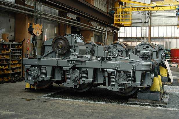
MECHANICAL PART A- BODY In order to standardize and simplify studies, CC6500 body is very similar to class CC72000 diesel locomotives, showing a power of 2650 kW and put into service from 1968. Body is made of two trusses linked by cross bars at the bottom and roof beams on top. Both ends are equipped with shield to protect the staff in the event of a collision. Both driving cabs are soundproof and equipped with functional control panel and heating systems. Their depth is reduced which did not allow fitting a more comfortable fix and adjustable seat like on more recent BB7236 and following for instance. Front windows are inclined to reduce glare. Glasses are 23 mm thick and equipped with washers. B-BOGIE Excellent results obtained on class CC40100 locomotives in terms of stability at high speeds since 1964, have encourage CC6500 designers to go further ahead in this direction. As a consequence, the CC6500 have received three axles single motor bogies (C type) derived from those of the 4 currents CC40100 in service on Northern lines. Each bogie is equipped with a TTB665 self-ventilated motor with double armature. Bogie consists in a tubular frame in thick steel sheet with crossbars, which carries motor and transmission casing. Transversally mounted motor drives a gear system which transmits the effort to the reducer via a Citroën flexible coupling. Reducer transmits the effort to axles via a cardan transmission. C- SUPENSION 1°) Primary suspension Primary suspension between axles and bogie is made by coil springs resting upon bracketson each side of axles bearings boxes. Movements of this suspension are dampened by shock absorbers. Vertical dampening of the suspension is made by 6 friction shock absorbers mounted between axles bearings boxes and bogie frame. 2°) Secondary suspension Body rests on bogie frame via 4 « sandwich » rubber blocks.These blocks meets the 3 functions of a pendular suspension : In addition two anti-yaw dampers link the bogie with the body. Below is a picture of a CC 6500 bogie. It is freshly painted which allows observing all suspension elements. |
|---|
|
|---|
Transmission of motor effort to the axles is made through 14 gears allowing use of the locomotive at two different maximum speed thanks to the two different ratios of the reducer. Lubrication of this transmission requires 6 oil pumps driven by intermediate gears. Pumps take the oil in the bogie side frame and direct it to parts needing lubrication via a piping system. Oil pumps PH1, PH3 et PH5 correspond to bogie 1. Their operation is controlled by 6 luminescent pictograms (PH) which must turn off soon after locomotive starts. Two pictograms are red, other four are yellow (See panel picture below). Reducer : Each bogie includes a 2 ratios reducer. Shift is done manually while locomotive is stopped with brakes on and main circuit breaker open. Reducers shift is done in the inside corridor by opening a door giving access to their control. Locking device is acted by a crank. Index on V (Locked) is taken to D (Unlocked). The same crank is used to act on the reducer changing ration system to bring it on wanted position PV (low speed) or GV (high speed): A neutral position (PM) exists and is used is some cases mentioned in the instruction manual. A large lever wrench is used to rotate motor rotor to position gears. Transmission from reducer to bogie : This transmission is "CARDAN" type with hollow shaft. While “Jacquemin” transmission transmits the effort to the driving gear with a single hollow shaft, on CC6500 locomotives, transmission uses two hollow shafts thus giving great transmission of the effort and traction flexibility. E- AXLES CC 6500 have one piece wheels, external bearing boxes which requires well visible shunts on bogie side for current return.Axles boxes are equipped with overheat sensors (vigithermes) ;In case of overheating, a red pictogram lights up on the panel. |
|---|
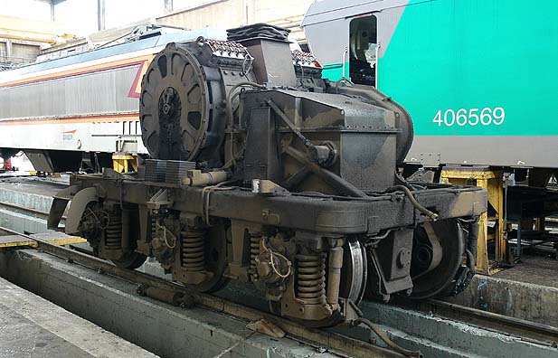 |
Bogie of a CC 6500 equipped with its TTB 665 motor. |
|---|
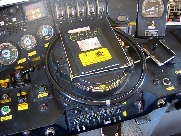
CC 6558 control panel. 6 pictograms PH1 to PH6 informing driver on correct oil pumps operation can be seen. On top part from left to right: Lower part: |
 |
|---|
TTB 665 motor includes 2 inductors and 2 armatures on a single shaft with individual commutators in the midle of the shaft. These motors are self cooled. CC 6500 have 2 power variators driven by a single actuator. 28 positions are used. The two J.20 and J.21 inverters as well as the two traction/braking switches may be driven manually by a lever located under lock box. 1°) Series coupling Series coupling is obtained by a lever located on the control panel. At the end of series coupling, power variators are in position 28. Series coupling is optional. It is used to limit intensity when locomotive starts on service tracks equipped with limited section overhead wire. To switch from series to series-parallel coupling, driver must put back traction control wheel at « zero » position and put series coupling lever on off. 2°) Series-parallel coupling If series coupling lever is on off position, start occurs on series-parallel coupling. At the end of series coupling, power variators are in position 28. 3°) Parallel coupling Variators in position 28 series-parallelthen switch to position 29, coupling motors in parallel resistances being inserted again. Resistances elimination takes place between variators positions 29 to 48. Control panel includes a variator position indicator with 2 windows: Starting rheostatis cooled by two groups of three fans each. These fans start once resistances are crossed by current. They stop when all resistances are eliminated from traction circuit. Anti-spin : Spin detection is made by comparing traction motors respective speeds with "ROCHAR" relays. When a spinning occurs, a pictogram appears on control panel, variators actuator stops progressing and sanding starts. In addition on series and series parallel couplings, contactors switch to the shunt motor rotor affected by spinning. This reinserts resistances that had been previously eliminated. HIGH VOLTAGE AUXLIARIES Batteries charging is done by a static converter. This converter produces a chopped current from 1500V DC current coming from overhead wires. This current provides power supply to a transformer primary which itself provides power to :
DYNAMIC BRAKING CC6500 are equipped with dynamic braking. It is used alone manually for slowing down or put on automatically during pneumatic braking. VARIOUS AUXILIARIES CC 6500 are equipped with :
|
|---|
CC 6500 MAINTENANCE CYCLE
CC6500 maintenance has been shared between depots of Lyon-Mouche, Paris Sud-Ouest and Vénissieux,in charge of regular maintenance, and Oullins maintenance center, in charge of heavy operations. In the eighties, during CC6500 heydays on South West lines, maintenance cycles were as follows: At this time, Oullins maintenance center was proceeding to: |
|---|
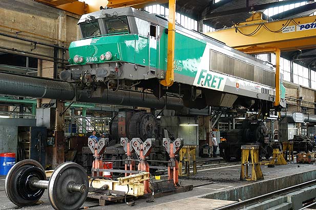
Impressive picture of CC6569 body being lifted in Venissieux depot workshop. (Photos Fabrice Douhet) |
 |
|---|